Quarter-Car Suspension Dynamics & Road-Disturbance Response
MATLAB project for passive quarter-car suspension dynamics, road-disturbance response, modal analysis, frequency response, and damping-sensitivity evaluation.
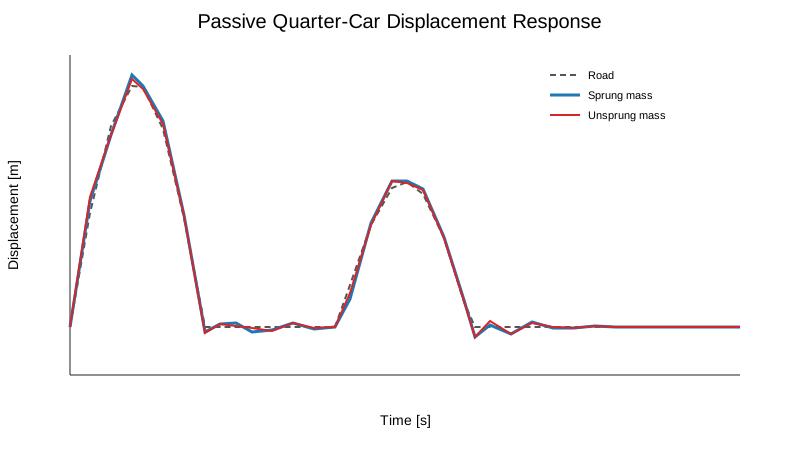
This MATLAB project studies the vertical response of a two-degree-of-freedom quarter-car suspension under a deterministic road disturbance. The public version preserves the archived four-state passive model and its source-derived parameters, then extends the analysis with modal checks, suspension-travel and tire-deflection metrics, direct road-to-body frequency response, and a clearly labelled damping-sensitivity study.
The complete MATLAB implementation, source audit, and generated numerical results are available here: GitHub repository
The archived simulation sets the inter-mass force input to zero. This page therefore presents a passive suspension study; it does not claim an active or optimal suspension controller.
Source-derived quarter-car model
The state vector is x = [zs, żs, zu, żu]ᵀ, where zs is sprung-mass displacement and zu is unsprung-mass displacement. The two model inputs are an inter-mass force and road displacement; the archived simulation uses zero force input.
| Parameter | Value |
|---|---|
| Sprung mass | 100 kg |
| Unsprung mass | 10 kg |
| Suspension stiffness | 200 N/m |
| Tire stiffness | 200 N/m |
| Suspension damping | 500 N·s/m |
| Control-force input | 0 N |
Passive stability
The source-derived nominal state matrix is asymptotically stable. The passive poles are approximately −54.2597, −0.4345, and −0.1529 ± 1.2935j; all real parts are negative.
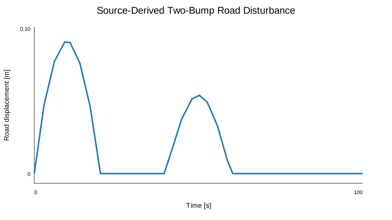
Road disturbance
The archived indexed input is represented by its continuous-time equivalent: a 0.10 m half-sine bump over 0–20 s followed by a 0.06 m half-sine bump over 40–60 s.
Body and wheel displacement response
| Nominal response metric | Value |
|---|---|
| Maximum road displacement | 0.100000 m |
| Maximum sprung displacement | 0.104200 m |
| Maximum unsprung displacement | 0.102653 m |
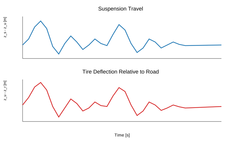
| Maximum suspension travel | 0.003710 m |
| Maximum tire deflection | 0.010590 m |
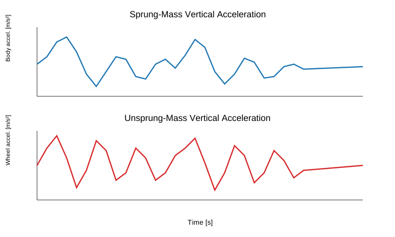
| Maximum |body acceleration| | 0.019350 m/s² |
| RMS body acceleration | 0.004920 m/s² |
| Peak body/road displacement ratio | 1.0420 |
Suspension travel and tire deflection
Vertical acceleration
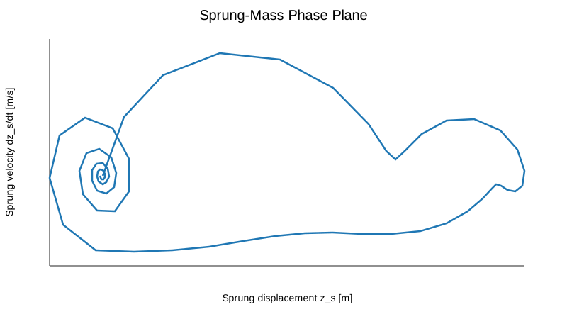
Phase-plane response
Road-to-body frequency response
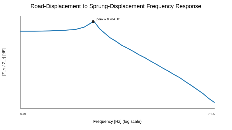
The modernization adds a direct numerical evaluation of H(jω) = C(jωI − A)⁻¹Br from road displacement to sprung-mass displacement. This analysis is new; it was not part of the archived script.
| Frequency-response metric | Value |
|---|---|
| Peak road-to-body magnitude | 4.619 |
| Peak magnitude | 13.29 dB |
| Frequency at peak | 0.2036 Hz |
These resonance values are properties of the archived academic parameter set and are not presented as validated production-vehicle suspension characteristics.
New damping-sensitivity analysis
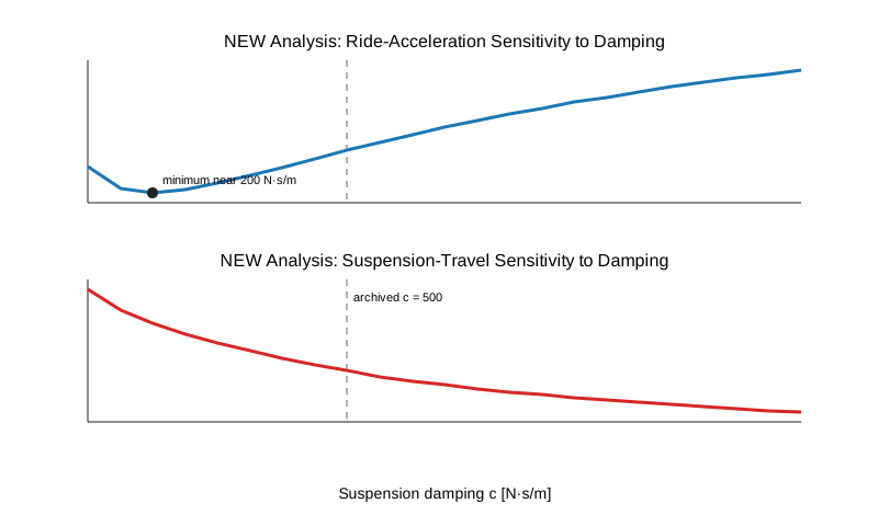
The archived nominal damping is c = 500 N·s/m. The cleaned project adds a sweep from 100 to 1200 N·s/m to expose the tradeoff between ride acceleration and suspension travel.
| Damping-sweep result | Value |
|---|---|
| Sweep range | 100–1200 N·s/m |
| Archived nominal damping | 500 N·s/m |
| Minimum-RMS-acceleration damping | 200 N·s/m |
| Minimum RMS body acceleration | 0.004288 m/s² |
For this specific road test, damping near 200 N·s/m minimizes RMS body acceleration, while increasing damping continues to reduce suspension travel. The archived 500 N·s/m value is therefore best interpreted as a compromise point, not as a uniquely optimal damping choice.
Scope and limitations
This is a linear two-degree-of-freedom quarter-car model using archived academic parameters. Suspension geometry, tire nonlinearity, bump stops, actuator dynamics, load transfer, and experimental parameter identification are outside its scope. The stiffness values are also much lower than typical automotive values, so the time scales and resonance should be interpreted only within this model. The archived control-force channel is present in the state-space equations but is fixed to zero in the validated experiment.
Reproducibility
The public repository contains the original archived suspension.m file as legacy material and a self-contained MATLAB runner that reproduces the passive response, metrics, frequency response, damping sweep, and figures without requiring additional toolboxes. The reported results were validated in MATLAB R2022b.